26GHz NYRD-805 Radar Level Meter
The NYRD805 radar level meter is a 26GHz high-frequency radar level
measuring instrument with a maximum measurement distance of 10
meters. The antenna is further optimized, and the new fast
microprocessor can perform higher-speed signal analysis and
processing, so that the instrument can be used in some complex
occasions such as steam, foam, dust, crystallization, condensation,
etc..
Radar Level Meter Technical Parameter
| Application | various corrosion liquid |
| Antenna material | PTFE |
| Measurement range | 10m |
| Frequency range | 26GHz |
| Accuracy | ±3mm |
| Medium temperature | -40C~130℃ |
| Process pressure | -0.1〜0.3MPa |
| Power supply | 24VDC (two lines, four lines) |
| Process connection | Thread, Flange |
| Protection grade | IP67 |
| Explosion-proof grade | Exia II C T6 Ga/ Exd ia IIC T6 Gb |
| Signal output | 4... 20mA/HART (two / four) RS485/Modbus... |
※ Note: Products can be customized according to the specific requirements of users!
Radar Level Meter Operating Principle
The radar level antenna emits narrow microwave pulses, which are
transmitted downward through the antenna. After the pulse touches
the surface of the measured medium, it is reflected back and
received by the antenna system again, and the signal is transmitted
to the electronic circuit part and automatically converted into a
level signal (because the pulse propagation speed is extremely
fast, the electromagnetic wave reaches the target and is reflected
back to the receiver. The time taken is almost instantaneous).
Radar Level Meter Design Features
◎ The antenna is small in size, easy to install; non-contact radar,
no wear and no pollution.
◎ Unaffected by corrosion, foam, water vapor, temperature and
pressure changes.
◎ The beam angle is small and the energy is concentrated, which
enhances the echo ability and helps to avoid interference.
◎ The measurement blind area is smaller, and it can also achieve
good results for small tank measurement.
◎ High signal-to-noise ratio for better performance even under
fluctuating conditions.
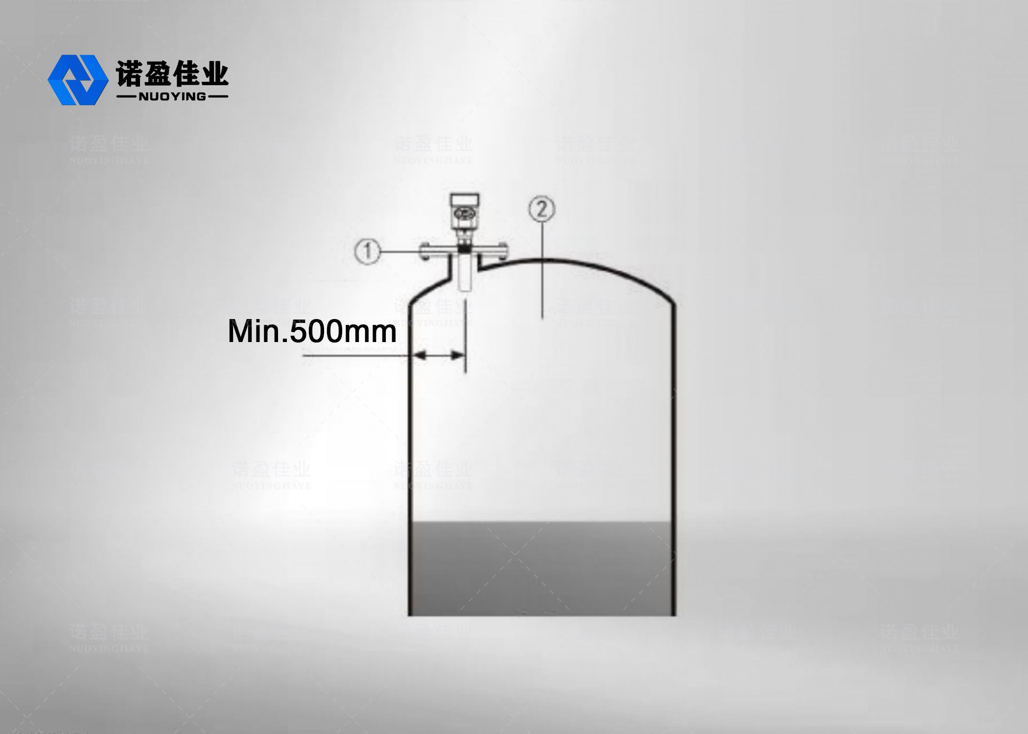
Radar Level Meter Installation requirements
- The radar level meter i s installed at 1 / 4 or 1 / 6 of the tank
diameter. Note: The minimum distance f rom the tank wall should be
500 mm : ①Datum plane , ②Containercenteroraxisofsymmetry.
Radar Level Meter Wrong installation
- The conical tank cannot be installed above the inlet .Note:
sunshade and rainproof measures should be taken when installing
outdoors. Figure 4 : ①Right, ②Wrong

- When there are obstacles in the tank that affect the measurement, a
reflector must be installed to measure normally. Figure
5:①Right,②Wrong
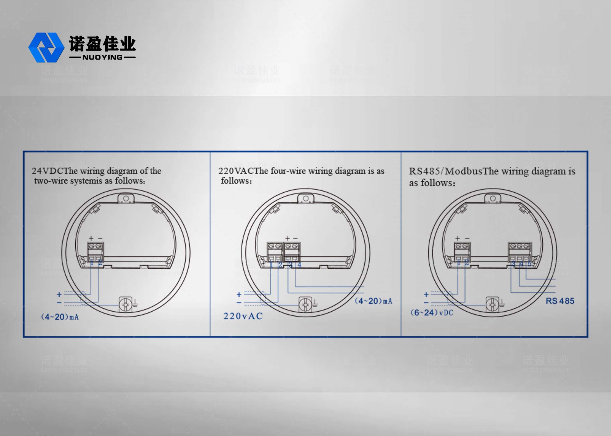
Radar Level Meter Electrical connections
Supply voltage
(4~20)mA/HART(Two-wire
The power supply and the output current signal share a two-core
shielded cable. Refer to the technical data for the specific supply
voltage range. For the intrinsically safe type, a safety barrier
must be added between the power supply and the instrument.
(4~20)mA/HART(Four-wire)
The power supply and the current signal are separated, and each
uses a two-core shielded wire. Refer to the
technical data for the specific supply voltage range.
The power supply and the Modbus signal are separated, and each uses
a two-core shielded wire. Refer to the
technical data for the specific supply voltage range.
Connection method
Radar Level Meter Protection Class
This instrument fully meets the requirements of protection class
IP66/67. Figure 6:
- How to Ensure Your Installation Meets IP67 Requirements:
- Make sure the sealing head is not damaged.
- Make sure the cable is not damaged.
- Make sure that the cables used meet the electrical connection
specifications. Bend the cable down before entering the electrical
interface to ensure that water does not flow into the housing, see
①
- Please tighten the cable gland,see②
- Please plug the unused electrical connections with blind plugs, see
③
Radar Level Meter Instrument debugging
The instrument has three debugging methods, as follows:
Method 1:Display/Key
The instrument is debugged through the 4 buttons on the display
screen. (Figure 7) ①LCD; ②Button.
Method 2:Host computer debugging
Connect to the upper camera through HART (Figure 8)
①RS232 Or USB;②Radar level meter;③HART adapter;④250Ωresistance
Method 3:HART handheld programmer programming
HART handheld programmer (Figure 9)
①RS232 Or USB;②Radar level meter;③250Ωresistance


